TPM Permanent Lifting Magnets
TPM Permanent Lifting Magnets
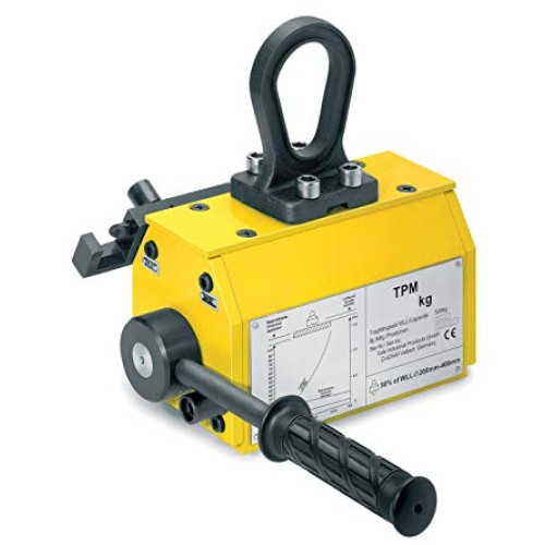
TPM permanent lifting magnets are ideal tools for easy, quick and economical transport of heavy objects made from ferro-magnetic material. Typical operating areas are workshops and warehouses, loading and unloading of machines as well as construction of jigs and fixtures.
Factors that reduce the magnetic clamping force:
Air gap:
High magnetic forces created by the TPM allow the magnet to clamp components through the air gap, however, air gaps will reduce the magnetic performance as they provide a barrier between the contact surfaces. Air gaps occur in a number of different ways such as paint, dust and heavy mill scale. Poorly machined surfaces also constitute an air gap. Please down rate the magnet capacity in accordance with the adhesive force/air gap diagram below.
Material thickness:
If the TPM is used to lift plates thinner than the recommended minimum thickness, the clamping forces will be significantly reduced. Performance curves can be identified in conjunction with the adhesive force/flat thickness diagram below:
Contact area
Full lifting capacity can only be achieved when the magnet has full contact area with the component being lifted. If the contact surface has holes in or is uneven then the performance will be affected accordingly. Always carry out a trial lift in these circumstances to establish correct lifting before transporting the load.
Material type:
Certain materials have different abilities to carry magnetism. For materials other than mild steel a reduction factor must be applied in order to calculate the effective clamping force.
| Model | Flat material- Max Capacity WLL KG*8 | Flat material - Min thickness to obtain max. WLL mm** | Flat material -MAX length of material mm | Round Material - Max capacity WLL kg ** | Round material - Diameter mm | Round material - Max length of material mm | Tear off force kg | Weight kg |
| TPM 0.1 | 100 | 14 | 2000 | 50 | 40 - 300 | 2000 | 300 | 5.3 |
| TPM 0.3 | 300 | 20 | 2500 | 150 | 60 - 300 | 2500 | 900 | 13.5 |
| TPM 0.5 | 500 | 24 | 3000 | 250 | 60 - 400 | 3000 | 1500 | 27.5 |
| TPM 0.8 | 800 | 34 | 3500 | 400 | 60 - 400 | 3500 | 2400 | 52 |
| TPM 1.0 | 1000 | 40 | 3500 | 500 | 80 - 400 | 3500 | 3000 | 57 |
| Model |
Flat material- Max Capacity WLL KG*8 |
Flat material - Min thickness to obtain max. WLL mm** |
Flat material -MAX length of material mm |
Round Material - Max capacity WLL kg ** |
Round material - Diameter mm |
Round material - Max length of material mm |
Tear off force kg |
Weight kg |
| TPM 0.1 | 100 | 14 | 2000 | 50 | 40 - 300 | 2000 | 300 | 5.3 |
| TPM 0.3 | 300 | 20 | 2500 | 150 | 60 - 300 | 2500 | 900 | 13.5 |
| TPM 0.5 | 500 | 24 | 3000 | 250 | 60 - 400 | 3000 | 1500 | 27.5 |
| TPM 0.8 | 800 | 34 | 3500 | 400 | 60 - 400 | 3500 | 2400 | 52 |
| TPM 1.0 | 1000 | 40 | 3500 | 500 | 80 - 400 | 3500 | 3000 | 57 |
** Maximum lifting capacity is achieved by using mild steels with the noted minimum thickness.
| Model |
A mm |
B mm |
C mm |
D mm |
kg |
| TPM 0.1 | 122 | 69 | 185 | 160 | 5.3 |
| TPM 0.3 | 192 | 95 | 225 | 250 | 13.5 |
| TPM 0.5 | 232 | 120 | 270 | 250 | 27.5 |
| TPM 0.8 | 302 | 154 | 320 | 450 | 52 |
| TPM 1.0 | 332 | 154 | 320 | 450 | 57 |
Typical values:
Ferrous alloy steels 0.8
High carbon steels 0.7
Cast iron 0.55
Examples of reduced WLL:
Mild steel 500g
Cast iron 500kg x 0.55 = 275kgs

